Saluki S1465V series vector signal generator features high-precision analog sweep function, excellent simulation modulation, pulse modulation and vector modulation. Three basic modes of signal can be output: continuous wave (CW) signal, sweep signal and digital modulation signal. If an internal baseband is used in the S1465V signal generator, vector modulation signals of bandwidth up to 200MHz can be generated. when an external I/Q is used, the modulation bandwidth is 200MHz, supporting broadband I/Q input of external arbitrary waveform generator, with RF modulation bandwidth up to 2GHz.
I/Q Modulation Introduction:
The function of the I/Q modulator is to load I and Q signals onto the carriers. The I/Q modulator consists of a symbol builder, a carrier local oscillator, a frequency mixer, a 90° phase shifter, and a linear superimposer. The symbol builder is responsible for converting the input modulation baseband signal into odd-even two-way signals through serial-to-parallel conversion. Therefore, the modulation method in the digital transmitter is actually determined by its symbol builder. Some literatures refer to the correspondence between information and carrying signals as “mapping”. The receiving end extracts the transmitted information from the received signal according to the mapping relationship previously agreed.
There are many ways to map information and signals. Different modulation techniques use different mapping methods. The main purpose of digital modulation is to control the transmission efficiency. Different digital modulation techniques are distinguished by their mapping methods and their performances are also determined by their mapping methods. This mapping relation is implemented by the symbol builder. The two frequency mixers, in-phase I and quadrature Q, are excited by the LO signals of the two local oscillators. The local oscillator signal of the lower frequency mixer is orthogonal to that of the upper frequency mixer, namely, the frequency mixers’ local oscillator carriers are orthogonal to each other. Then the outputs of the two frequency mixers are mixed.
Note that the I/Q modulator uses analog technique (RF frequency mixer and RF synthesizer) and monolithic microwave integrated circuit MMIC, and even it is implemented in the DSP. The I/Q modulator changes the control problem from signal phases to two-way orthogonal component voltages. The I/Q indicates the orthogonal transformation of the modulated signal. The Q component signal is phase-shifted by 90 degrees with respect to the carrier. If only the I channel is used for detection, the I output is 0 V although the Q input signal exists because of cos(90°) =0 and there is no output signal in the I channel. Therefore, a vector-modulated signal can be generated by linearly superimposing the signal in-phase and quadrature components, without worrying that the I and Q components interfere with each other. For wireless transmission, it shall be sent out after being added (Σ) and synthesized.
S1465V I/Q Modulation Setting:
Press [I/Q] key in front panel or click [I/Q] menu item in user interface, and an I/Q-related menu will pop up to enable you to set I/Q-related parameters. The main operation dialogs are as follows:
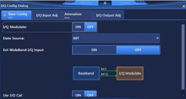
1. Base Config
Base Config Dialog, shown in Fig.1, enables you to set parameters such as I/Q Modulate ON/OFF, Data Source and Ext WideBand I/Q Input ON/OFF. Data Source includes EXT50Ω and INT.

Fig.1 Base config dialog
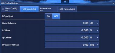
2. I/Q Input Adj
I/Q Input Adj Dialog, shown in Fig.2, enables you to set parameters such as I/Q Adjust ON/OFF, Gain Balance, I Offset, Q Offset and Orthority Offset.

Fig.2 I/Q Input adj dialog
3. Attenuation
Attenuation Dialog, shown in Fig.3, mainly includes Modulation Attenuation. Attenuation can be set in Manual mode.

Fig.3 Attenuation dialog
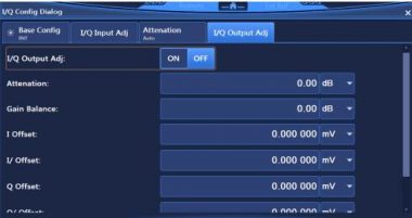
4. I/Q Output Adj
I/Q Output Adj Dialog, shown in Fig.4, enables you to set parameters such as I/Q Output Adj ON/OFF, Attenuation, Gain Balance, I Offset, I/ Offset, Q Offset, Q/ Offset.

Fig.4 I/Q output adj dialog


