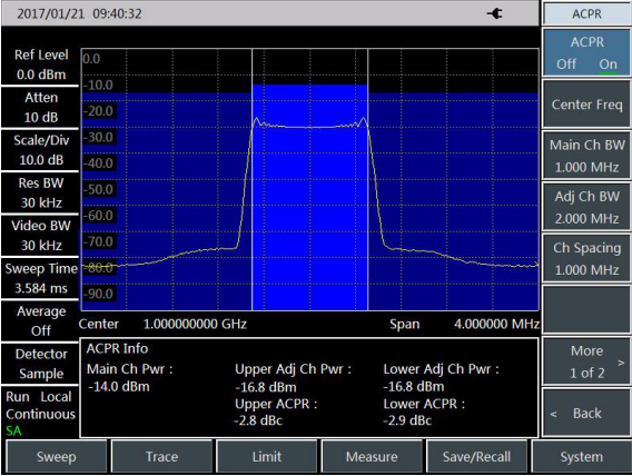
All Saluki RF spectrum analyzers support ACPR measurement functions. So what is ACPR function? How to use this function on spectrum analyzers? How to operate? In this article, we will show the ACPR measurement operation of S3302 series handheld spectrum analyzer.
What is ACPR?
The adjacent channel power ratio (ACPR), also known as the adjacent channel leakage power ratio (ACLR) refers to the ratio of the transmitted power of one channel to the radiation power of the adjacent channel. It is generally expressed as the ratio of the power within the specified bandwidth under various offsets of the adjacent channel to the total power of the channel. The adjacent channel power mainly depends on the extension of the modulated sideband and noise of the transmitter.

Definition of ACPR (Screenshot Taken from S3302 Handheld Spectrum Analyzer)
The adjacent channel power ratio measurement can be applied, as a substitute of the traditional dual-audio IM distortion measurement, in nonlinear system tests. The measurement result of the adjacent channel power ratio can be expressed in two forms: power ratio and power density.
Measurement procedures
In the traditional measurement of the narrow-band signal, the distortion performance of the transmitter is evaluated generally by means of dual-audio signal IM measurement. The broadband modulation signal includes both the dense spectrum components and high peak signal (also known as the crest factor). IM products of spectrum components of the signal are always around the spectrum. The IM measurement of the broadband FM signal is complex, while ACPR is closely related to IM products arising from nonlinear distortion. Therefore, ACPR is a better method to measure the nonlinear distortion of the broadband FM signal.
The ACPR of the broadband FM signal can be measured with the ACPR measurement function of S3302 series spectrum analyzer according to the following procedures.
1) Set the signal generator to output the broadband FM signal:
Use the signal generator to generate one FM signal. Set the frequency as 1GHz, power as -10dBm, FM offset as 500kHz and demodulation rate as 10kHz. Connect the output of the signal generator to the RF input end of the spectrum analyzer through one cable, as shown in Fig. 4-1. Enable the ON state of the modulation output and radio frequency.
2) Reset the spectrum analyzer into the default state:
Press [Reset].
3) Set the reference level of the spectrum analyzer:
Press [Amplitude] , [Ref Level] and -10[dBm];
Press [Amplitude] and [Scale/Div] and set the scale as 10dB/division.
4) Set the resolution bandwidth and video bandwidth:
Press [BW] and [RBW Auto Man], and set the resolution bandwidth as 30kHz;
Press [BW] and [VBW Auto Man], and set the video bandwidth as 30kHz or less.
5) Enable the ACPR measurement:
Press [Measure], [ACPR] and [ACPR Off On] to enable the ACPR interface.
6) Set the center frequency of the main channel:
Press [Center Freq] and set the center frequency of the main channel with number keys, i.e. 1GHz.
7) Set the bandwidth of the main channel:
Press [Main Ch BW] and set the bandwidth of the main channel with number keys, i.e. 1MHz.
8) Set the adjacent channel bandwidth:
Press [Adj Ch BW] and set the adjacent channel bandwidth with number keys, i.e. 2MHz.
9) Set the channel spacing:
Press [Ch Spacing] and set the channel spacing as 1MHz with number keys.
10) Enable the ACPR test:
Press [ACPR Off On]. Then the measurement results will be displayed at the bottom of the screen. Refer to Fig. 3 for the schematic diagram of ACPR measurement.
11) Limit setting:
The limit test function can be applied so as to easily observe whether the adjacent channel power is beyond the set range. Press [Measure], [ACPR] and [More 1/2] to enter the ACPR limit test setting menu.
Press [Upper Limit] and enter the upper limit with number keys.
Press [Lower Limit] and enter the lower limit with number keys.
12) Enable the limit test function:
Press [Limit Test Off On] to enable the limit test function. If the adjacent channel power is beyond the set limits, the screen background will become red for indication.


