Experiment name: Application of power amplifier in forward and reverse motion experiments of bending composite ultrasonic motors excited by a single signal
Research direction: Ultrasonic motor
Experimental content: Use a single-channel special excitation signal (composed of two sinusoidal waveforms with a frequency ratio of 1:2) to drive the bending composite ultrasonic motor and test the movement trajectory of its driving foot and the basic output characteristics of the prototype.
Experimental purpose: To verify the feasibility of the working principle of the ultrasonic motor based on the 8-shaped vibration trajectory.
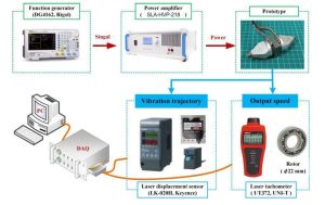
Test equipment: Function signal generator, SLA-HVP-218 power amplifier, laser displacement sensor, laser tachometer, etc.
Experiment procedure:
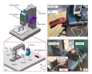
(1) Test drive foot trajectory. Use two laser displacement sensors to align the upper and lower surfaces of the driving foot respectively, use a powerful signal amplifier to generate a signal, amplify it with the power amplifier SLA-HVP-218 and apply it to the ultrasonic motor, turn on the sensor acquisition function, and complete Vibration trajectory collection. Change the phase difference between the two signals in the excitation signal, from 0^360 degrees, and test every 15 degrees, for a total of 24 times.

Experimental device
(2) Test output characteristics. Place a small pulley at the driving foot with luminous paper on the side. Turn the pulley for one revolution and observe whether the tachometer counts normally. Then use a signal generator and power amplifier to generate an excitation signal and apply it to the ultrasonic motor. Test the motor in different waveforms. (the phase difference between the sinusoids of the two frequency components).

Test Results:
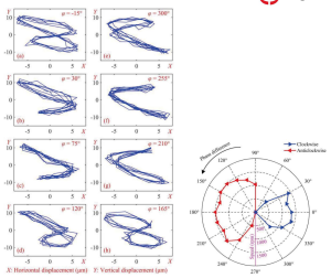
1. The driving foot can obtain a figure-8 trajectory when the waveform phase difference is 165 degrees and -15 degrees, and the movement direction of the trajectory is opposite:
2. The proposed ultrasonic motor based on the figure-8 trajectory has a difference in forward and reverse output characteristics of less than 4%, and the maximum output speed when pushing a rotor with a diameter of 22m is 1373rpm.
3. The proposed ultrasonic motor based on a figure-eight trajectory can achieve bidirectional output motion with only a unidirectional excitation signal. The piezoelectric elements are not idle and the friction coupling efficiency is high. It has potential application value in high-reliability applications such as aerospace and aerospace.

Track motion test results Mechanical output characteristics test results
The effectiveness of the power amplifier in this experiment: driving the motor to achieve oscillatory motion.


