Saluki S3101 cable and Antenna Analyzer is a kind of handheld cable and antenna analyzers. Handheld cable and antenna analyzer helps field technicians perform field verification and fault location to detect problems before they become costly, time-consuming system failures. S3101 cable and antenna analyzer can boosts your efficiency of troubleshooting and testing speed.
In order to understand the performance of the transmission system and solve the common problems in the transmission line system, S3101 cable and antenna analyzer provides measurement functions for cable & antenna diagnosis. It can offer measurement capabilities including precision return loss/VSWR, cable loss and distance-to-fault (DTF) measurements. This paper will introduce the operating procedures for cable & antenna test in detail.
Return Loss Measurement Setting
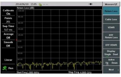
1) Press [Meas] key, click [Return Loss] menu to set the instrument measurement format as return loss.
2) Press [Freq/Dist] key and input the frequency range to be measured, that is start frequency and stop frequency.
3) Press [Cal] key to select the appropriate calibration kit to complete the calibration.
4) Connect the Analyzer to the DUT of which the terminal is antenna (in return loss measurement, DUT shall connect the load).
5) Press [Ampt] key and input the top-bottom coordinate figure or directly select the auto scale, to facilitate a better observation of measurement curve.
6) Press [Marker] key to set the appropriate marker.
7) Press [Limit] key to set a appropriate limit line.
8) Press [Save/Recall] key to store the current measurement results to the memory to facilitate later recall.

Fig.1 S3101 return loss measurement
Cable Loss Measurement Setting
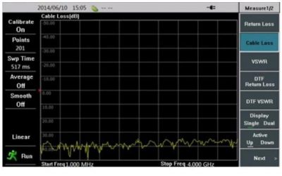
1) Press [Meas] key, click [Cable Loss] menu to set the instrument measurement format as cable loss.
2) Press [Freq/Dist] key and input the frequency range to be measured, that is start frequency and stop frequency.
3) Press [Cal] key to select the appropriate calibration kit to complete the calibration.
4) Connect the Analyzer to the DUT of which the terminal is antenna (in cable loss measurement, DUT shall connect the short circuit).
5) Press [Ampt] key and input the top-bottom coordinate figure or directly select the auto scale, to facilitate a better observation of measurement curve.
6) Press [Marker]] key to set the appropriate marker.
7) Press [Limit] key to set an appropriate limit line.
8) Press [Save/Recall] key to store the current measurement results to the memory to facilitate later recall.

Fig.2 S3101 cable loss measurement
Distance-To-Fault (DTF) Measurement Setting
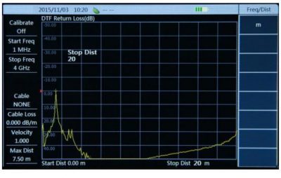
In S3101 Cable & Antenna Analyzer, DTF measurement has two different display formats: DTF Return Loss and DTF VSWR. For the two same measurement processes, follow these steps to set. 1) Press [Meas] key to set the instrument measurement format as DTF Return Loss or DTF VSWR.
2) Press [Freq/Dist] key to first input the frequency range to be measured, that is start frequency and stop frequency; and then the distance range to be measured, that is start distance and stop distance; and also select the model of cable measured or input the cable velocity factor and cable loss.
3) Press [Cal] key to select the appropriate calibration kit to complete the calibration.
4) Connect the Analyzer to the DUT of which the terminal is antenna.
5) Press[Ampt] key and input the top-bottom coordinate figure or directly select the auto scale, to facilitate a better observation of measurement curve.
6) Press [Marker] key to set the appropriate marker.
7) Press [Save/Recall] key to store the current measurement results to the memory to facilitate later recall.

Fig.3 S3101 DTF measurement


